
Task
Design and produce automatic locker’s electronics system that allows to control section doors and set of sensors via PC.

Creating process
Task analysis and collecting requirements.
According interview several models of basic architectures was offered. Each controller can handle one or several doors. For less complex each locker box control task we offered controller solution that is able to handle up to 9 locker boxes. This architecture was closer to legacy systems one. For more complicated task – more sensors and business logic on each box – single controller per door was offered.
Client has chosen 9 box controller, but requested for possibility to connect expansion board for more sensors or additional business logic.
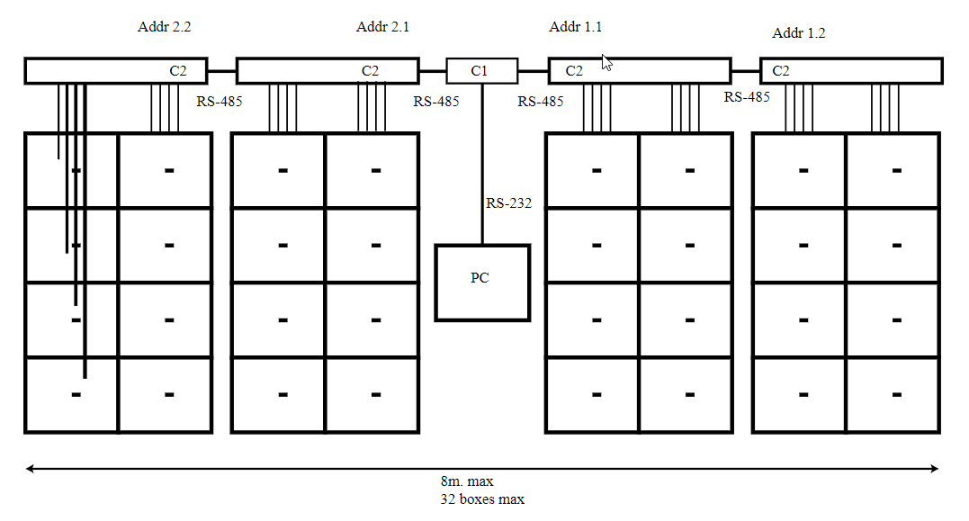
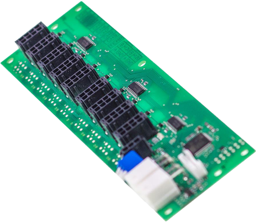
In many cases locker system might have more than 9 locker boxes. For this reason several controllers (C2) are connected to RS-485 network. Converter RS-485 – RS-232 is designed to connect system to PC.
PCB design

Programming
According requirements locker controller must have possibility to update it’s firmware remotely and this process must be safe and under control. For this reason plugin architecture was used.
Description
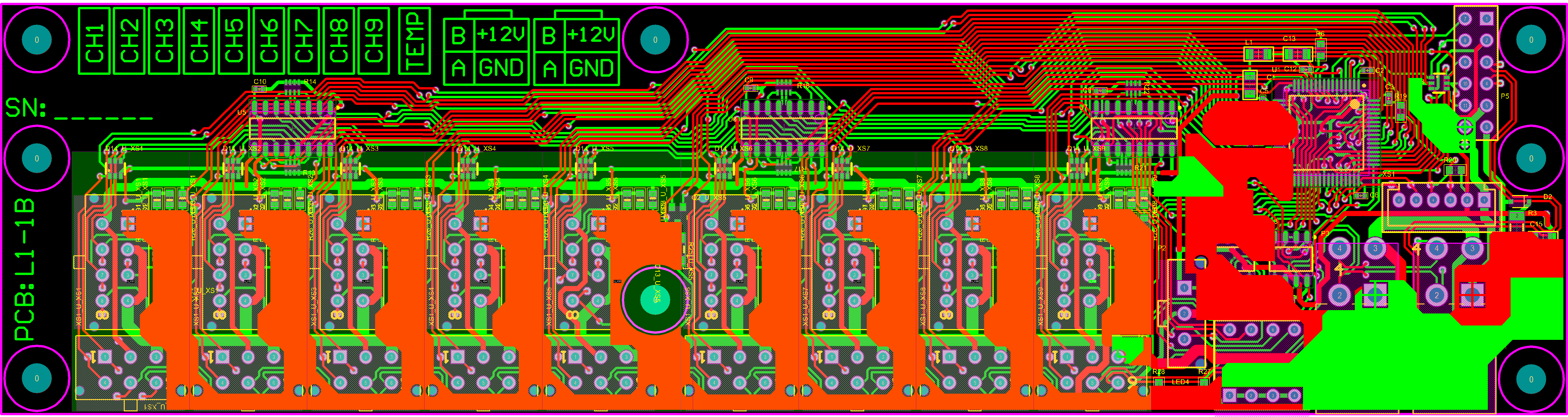
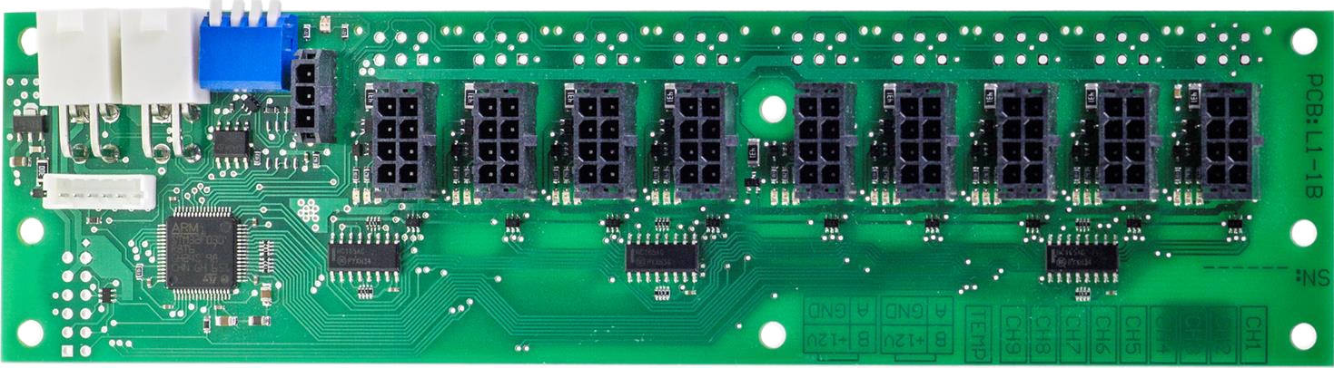
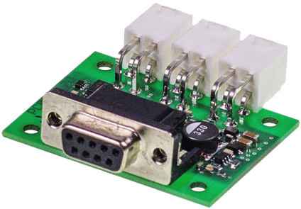
Automatic locker controller (LC) is designed to control up to 9 electromechanical lockers with illumination LEDs and receives commands/ transmits status via RS485 line.
Main electrical locker controller data:
| Supply voltage | 12VDC (8-24VDC possible) |
| Current consumption | <40 mA (15 mA typ.) |
| Locker mover control output | pull type: 12V, <0.1A |
| LED output | push type via 1k resistor |
| Interface type | RS485: 115kbps |
| Device address range | 0-15, via DIP switch |
LC has additional input for external digital thermometer (DS18B20) connection.
LC is based on STM32F030R8T6 (Cortex M0, working at 32MHz) microcontroller and uses 74HC165 registers, as I/O extender. All LC input lines are protected with 3.3V TVS diodes (for RS485 line 5V TVS diodes are used). States of both inputs and state of locker mover control output are indicated by on-board LED’s. Internal device supply voltage, 3.3V, is made from 12V supply via linear regulator due to very low supply current, which is only 15mA typical.
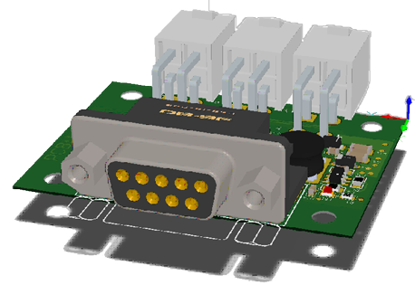
To connect LC to host computer RS232/RS485 isolated converter is used. Main electrical converter data:
Main electrical LC data:
| Supply voltage | 12VDC (8-24VDC possible) |
| Current consumption | <60 mA @12V (50 mA @12V typ.) |
| Maximal data rate | 460 ksps |
| RS232 lines used | TxD(2), RxD(3) |
| Isolation voltage | RS485: 115kbps |
| Device address range | 2.5kV (for 1 minute), 425V (50 years) |
Supply voltage to converter is connected from LC side. Isolation barrier is based on Analog Devices ADM3251E. Due to significant consumption, switching 12v->5V regulator is used.