Purpose
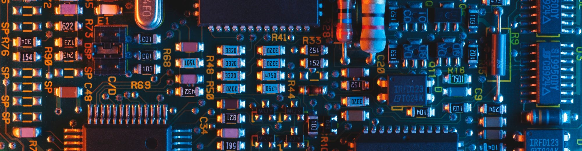
Safe ticket transportation machine (TTM) is responsible for ticket collecting from point of sale equipment, transportation, and purging them to storage machine.
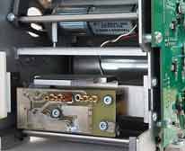
Figure 1. Fragment of TTM machine
Task
Increase communication with peripheral devices stability. Fix ticket collecting engine. All should be done with minimum (or without if possible) changes in electronic. In case of not enough technical data reverse engineering should be performed.
Process
Firmware
Initial software version is V14.07 (V14.10 source code is not available). The following things noticed to be corrected:
-
- ULFbus requires a lot of processor resources. In old Ulfbus code, whole packet transmission and delays with “while()” functions was implemented in interrupt service routine. This blocks main program execution for significant time. PID algorithm and motor management also need exact timing. ULFbus code is rewritten in such a way: delays are implemented with Timer generated interrupts, ULFBus bit transfer is implemented with pin interrupts.
-
- FreeRTOS is updated to the newest version.
-
- Big delays in „MSGParser“ task were implemented as „while()“ loops (~0.7sec.). This blocks other tasks with lower priority and wastes processor time.
-
- UART output was implemented in separate task with blocking style functions (wastes procesor time for waiting byte to be transmitted). Almost all UART output is dissabled in release version of V4.07 software.
-
- Output to LCD was implemented in dedicated task. There is no need for separate task, because LCD output functions are fast enough.
-
- “Pest” and “Protection” tasks were not loaded enough.
-
- OS tasks code style was complicated, because tasks sent events to themselves, OS timers were not used for timeout generation.
-
- LED frequency measuring and external set point for PID calculating functions have an error, which caused short spikes of external set point value.
-
- I2C bus communication errors were frequently observed.
- Note flash memory was used without CRC checking. The CRC code was written, but not used.
Changes that have been implemented in new version:
-
- FreeRTOS updated to the newest version.
-
- Tasks were rewritten completely, because
-
- LCD and UART tasks were removed. New functions were created for data output to LCD and UART.
-
- “Pest” and “Protection” tasks merged to a single one.
-
- UART command line interface for debugging and hardware equipment testing was created.
-
- ULF bus code was modified: delays implemented via Timer interrupts, bit transmission uses pin interrupts, also.
-
- New functions implemented for I2C bus and flash memory management.
- Note flash memory CRC checking was turned on.
Features that could be implemented:
-
- Error message will not be displayed on LCD if note flash memory cell will corrupt. Strange TTM behavior will be observed. Note flash memory use is very intense, all note flash memory is rewritten on every incoming and outgoing note. The corresponding error message or simple file system functionality is desirable in case with possible note flash memory corruption.
-
- Quartz oscillator circuits are not reliable in NXP microcontrollers. If main oscillator fails, TTM will not start at all. It is possible to write code which displays error in this situation, because microcontroller runs from internal RC oscillator at startup.
- When an error occurs, TTM displays only error code on LCD. It would be more convenient for user to see error text.
Electronics
-
- It is designed and fabricated external Flash memory logger, which is connected to TTM UART bus. It logs TTM start moment, errors and ink activation with tie stamp. It is essential to have real time in logs. For this reason, the battery holder should be soldered into the board and RTC should be set up via UART command line.
-
- Battery holder and CR2032 are needed for real time functionality.
-
- Gate voltage of Q1 FET is near the threshold value. R12 value should be decreased.
- Reset by pushing four keys simultaneously was not possible activate on some TTM. More accurate test is needed to clarify situation.
- Signal and power ground separated in connector.

Figure 2. Signal and data ground in one contact
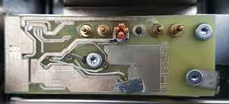
Figure 3. Signal and data ground in separate contats
Mechanics
-
- Each of three motor cylinders has a roller ahead of them, which guides film to center of cylinder. This is not true for back motor cylinder. The roller near the back motor cylinder is wider than cylinder, consequently film touches cylinder’s edge and slows motion.
- When note collect process is in progress, master sets film velocity for TTM so high, that required motor power is approx. 85%. TTM must ensure film tension over entire process. The power margin is too small. PID logs show, that motor power reaches 100% some times. It is suggested to increase supply voltage in order to have bigger power margin.