
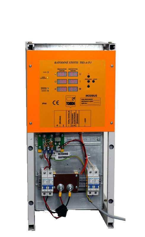
Figure 1 Cathodic protection station rev. 1
Aapplication
Cathodic protection allows to control corrosion in metal. There are several methods of cathodic protection – galvanic and impressed current. We have designed system that protects pipelines against corrosion using impressed current cathodic protection method (ICCP).
Technical description
Operating mode is automatically selected upon three main limiting set points: reference potential, current and voltage. Control is performed according to one of them, witch is reached first, due to load nature. Other two set points acts as limiting values.
Currently we provide new version of system based on knowledge collected during sale and maintenance our previous version of cathodic protection station and some innovations in electronic components market.
| Operating temperature | -40C..+50C..+70C( 60% of power) |
| Power | 250W, 500W, 1.5 kW |
| Output voltage | 0..50V |
| Current output | 0..5A, 0-10A, 0-30A |
| Power supply | 160 ~ 264VAC |
| Power factor | >0.95 @220V |
| Efficiency at full power | >0.86 (>0.9 dėl 1.5kW) |
| Isolation voltage primary – secondary circuit and secondary circuit – potential measurement | 1.5kV |
| Working mode | constant potential, |
| constant voltage, | |
| constant current, | |
| potential relaxation time measurement | |
| Potential measurement input impedance | 30 MΩ |
| Indication | OLED display |
| Working mode parameters logging interval | according to configuration starting since 10s |
| Telemetry | Modbus protocol over: |
| GPRS | |
| dial-up | |
| RS232 | |
| Integrated key for potential relaxation measurement | |
| Time sinchronisation according GPS module | |
| Embedded Linux OS in control/communication unit.
|
|
Supported software
Station remote monitoring and control software KSC2008:
- Microsoft.NET based, works on Windows OS.
- Collects data via GSM modem connection.
- Allows to monitor (read) or set station output parameters, read data from the station
internal parameters storage. - Data history stored to Microsoft SQL Server or MSDE database (with possibility
of stored data access from 3rd party tools). - Stored station data history may be drawn on the display or even printed.
- Possibility to connect directly to the station for observing real-time parameters.
Process of creation
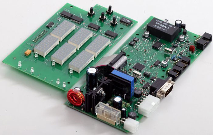
Figure 2 Cathodic protection station controller version 1
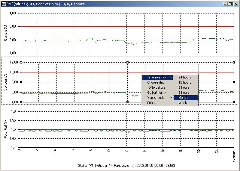
Figure 3 Current, voltage and support potential graph
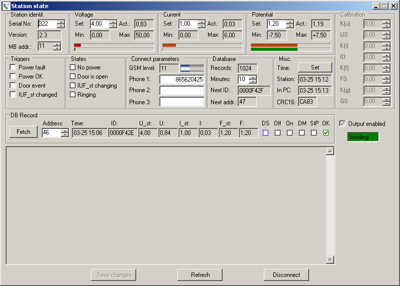
Figure 4 Cathodic protection station settings
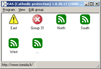
Figure 5 Remote cathodic protection state and selection
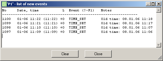
Figure 6 Station event handling
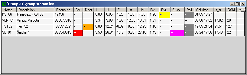
Figure 7 Station grouping
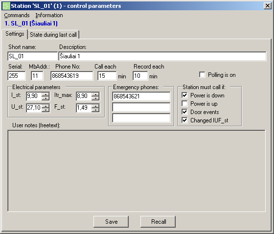
Figure 8 Station call server serrings