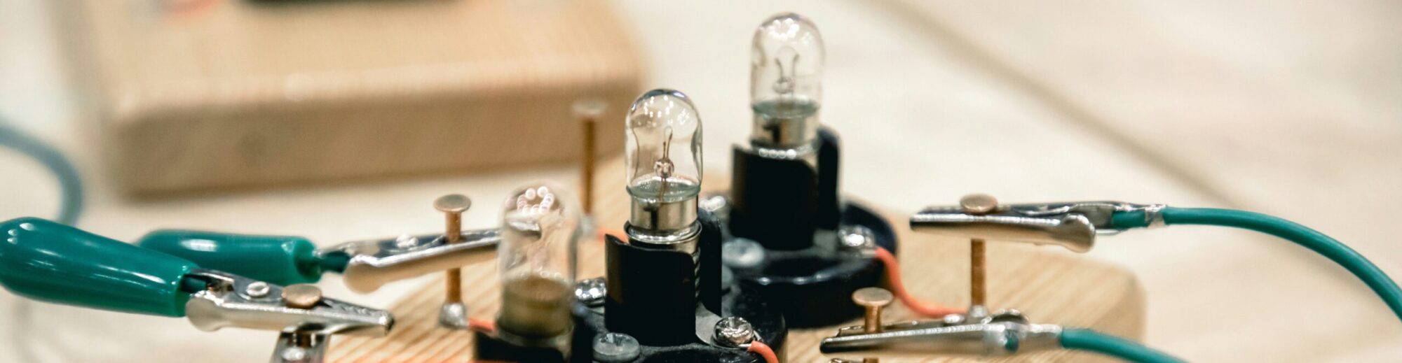
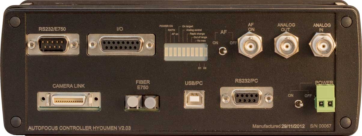
Figure 1 Fast autofocus system controller
Application
The Autofocus system is used to keep the laser beam focus exactly on the changeable sample surface. The controller for fast autofocus is designed to keep constant distance between objective-lens and the sample surface of the object by processing signal from CCD camera and to generate error signal to be used to correct position of the objective lens with the help of piezo actuator. (see figure 2).
Figure 2 Autofocus schema
Microscope Objective (1) is fixed to piezo stage actuator (2), which allows positioning of the objective in z-coordinate. The laser beam reflected from sample is collected by objective and directed to the linear CCD camera (3). The linear CCD camera gives us the optical intensity close to a Gaussian profile. The beam profile very much depends on surface type.
The linear CCD camera transfers the optical signal into the electrical signal (interface (4)) and sends it to the controller of autofocus system (cable (5)). The controller of autofocus system has microcontroller (6). DSP (Digital Signal Processing) microcontroller scans all 4096 pixels of the linear CCD camera, converts them into digital data and filters electrical and optical noise and finds intensity maximum position. Then the position data is passed to Piezo Stage Controller via fiber connection (7). The controller of the Piezo Stage Actuator (8) moves objective in vertical axis, returning the objective to the required position. Thus Auto Focus System has negative feedback loop control, which enables to keep constant distance from surface.
To eliminate noise and to get intensity maximum position the controller of autofocus system uses a very fast Spline smoothing algorithm. Spline parameter (number of averaged pixels) can be predefined by user from PC (see user’s interface). This enables to make parallel real time calculations during readout of the linear CCD camera’s pixels (0…4096) at 30 MHz clock rate. Total closed loop feedback delay is less than 1 ms.
Technical description of Autofocus system controller
| No. | Properties | Specifications |
| 1. |
Controller Interfaces |
|
| 1.1 | Camera P2-22-04k30 or P2-22-04k40 2 channel Camera LinkTM (LVDS signal) | Camera’s resolution 4096 pixel, data format – 8 bits |
| 1.2 | RS232 | for E-750 piezo controller |
| 1.3 | Optical fiber interface | for E-750 piezo controller |
| 1.4 | Main analog output: | for analog E-750 AUX IN connectorOutput voltage: 0 – 4.5 V;- Minimum load impedance: 5 kohm- Resolution 16 bit- Differential nonlinearity <1 bit- Update rate >1kHz |
| 1.5 | Analog input:BNC connector | Input voltage: 0-10 VImpedance: >15 kohmResolution 16 bit |
| Analog output for laser intensity control | – Resolution 12 bit- Minimum load impedance: 5 kohm | |
| 1.6 | Power supply | 24 V DC, < 8 W |
| 1.7 | Interface to PC | RS232, 115.2 kBod 8N1USB 2.0 |
| 1.8 | Logical input/output (configurable polarity) | – Input: switch on autofocus- Output: no maximum found- Output: position out of range- Output, active when autofocusing is ON, mass center position is found and deviation is lower than PZT max jump (separate BNC connector) |
| 2. |
Main components |
|
| 2.1 | Processor | Analog Device 16/32 bit DSP Blackfin ADSP-BF532 400 MHz (800 MMAC) as frame grabber and mass center calculator & LPC2368 (ARM7, 72MHz) for PZ position regulation, information registration and interconnection control . |
| 2.2 | DAC | type AD5542CRZ |
| 2.3 | Process monitoring system | MMC cardData recorded for each Dalsa frame:1. First mass center position. (1.5 bytes)2. Second mass center position. (1.5)3. First curve width (1.5)4. Second curve width (1.5)3. Current PI position (3)4. Command to PI (3)5. AF controller status (1)
7. Maximal illumination level (1) 8. Background level (1) Also, each new measurement records information about working mode. (set point, configuration)
|
| 3. | Algorithms, modes and indications | |
| 3.1 | Displacement control algorithm | PI is controlled according mass center position movement, calculated from reflected beam intensity profile. Regulation can be made according proportional or proportional-integral algorithms.In case PI works in close loop mode – then only proportional method is meaningful; in case of open loop mode Proportional Integral or Proportional Integral Differential regulation with notch filter will be implemented.Some other regulation algorithm features:1.For large displacements response is nonlinear (two sensitivity regions or x2 algorithm)2. For very small displacement response is zero3. In case of mass center displacement larger than MaxPZTJump, PI control signal ‘freezes’.4. For “no signal” condition response is zero. |
| 3.2 | Indications and outputs (polarity is configured) | – On Target- Switch On autofocus LED- error: maximum was not found in a whole line- error: maximum is out of limit-warning: maximum’s position is rapidly changing- autofocus is switched on/off |
| 3.3 | Working modes | – manual control via PC to send position (without feedback)- autofocus to required position (with feedback)- calibration- distance readout to PC without focusing- configuration- Change of DSP program from PC (e.g. change of algorithm to find maximum of intensity) |
| 3.4 | Max duration of line readout and analysis | Depends on chosen algorithm,In case of mass centre calculations, <80 µs |
| 3.5 | Repetition rate of commands sent to piezo actuator controller analog input | could be configured up to 5Khz via DALSA frame rate |
| 5. | Approximate dimensions | 120 mm * 150 mm * 60 mm |
| 6. | Case | “Bopla” ABD 2070 |
Creation process
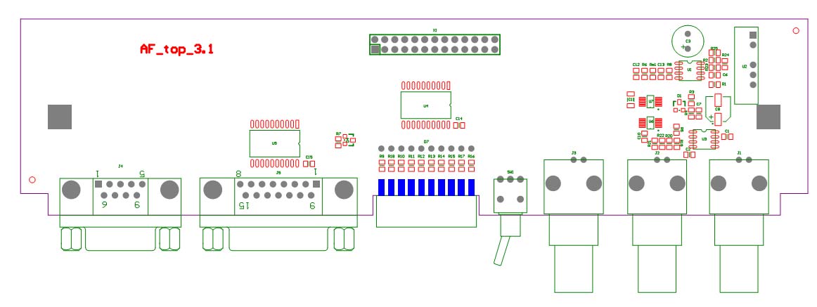
Figure 3 Controller for fast autofocus system top PCB
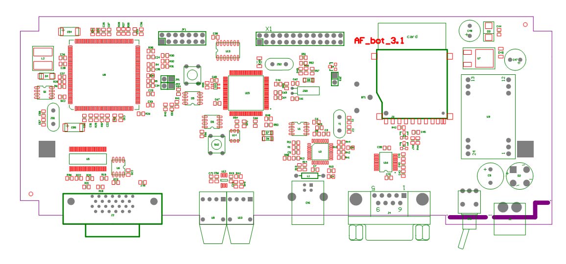
Figure 4 Controller for fast autofocus system bottom PCB
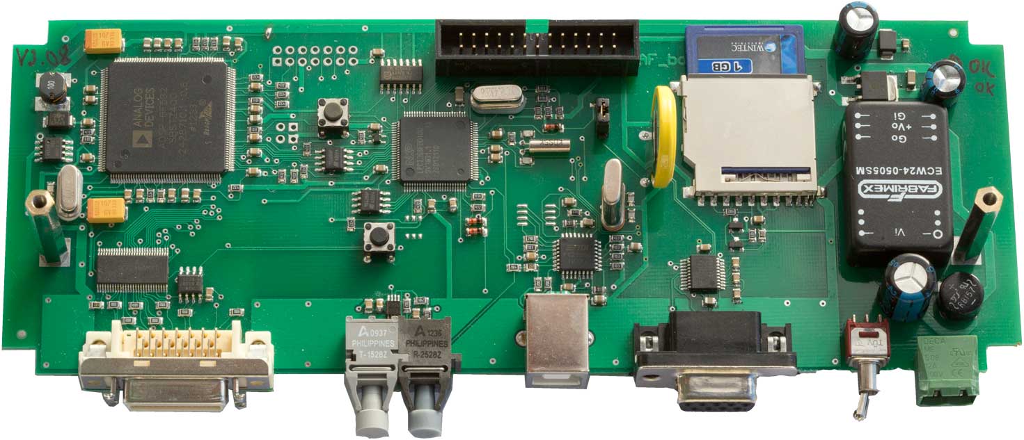
Figure 5 PCB production board